woensdag 22 juli 2015

Reducing mdadm speed for USB-RAID on RPi2.

Last few days I've had a problem. At certain moments my LAN interface on my RPi2 stopped working, making the RPi2 unreachable from the network.
The LAN interface internally runs on the same USB controller as the USB-ports. To debug my problems I've reduced my throughput to my USB flashdrives to 400kbit/s to offload the USB a bit.

As root/su user I've given the next commands. The first reduces the throughput to around 400kbit/s the second one is to make sure a 10kbit/s throughput is guaranteed.

echo 400 > /proc/sys/dev/raid/speed_limit_max
echo 10 > /proc/sys/dev/raid/speed_limit_min
The result is a reduced throughput as expected. Now hope it will fix my problems.

Update: Problem not solved. Crunching brain to see what to do next. However speed was reduced, so I will keep this blog post online. Partial success.

Update2: Problem solved. 
I run my Pi via an Adafruit Powerboost 500c. While the output power of this device is enough the charge rate isn't. So the LiPo battery slowly drains. The product page already warned me. When the voltage is too low, the Pi dies and does not reboot. After that the battery charges again because of the lower current demand of the Pi that's not running anymore. I've modified my Powerboost 500c to get a charge rate of 600mA (out of spec), and now the setup runs fine for >10 days already. Time to upgrade to a Powerboost 1000c.


dinsdag 26 mei 2015

Kenwood TM-D700 control head cable.

Recently I've changed my mobile tranceiver from a Kenwood TM-D700 to a Yaesu FTM-400D.

With all the cables of the old installation still in the car, I needed a new separation cable to connect the control head on my TM-D700. After some hours looking for the proper layout of such a cable I've just found some text and no pictures. And because pictures say more than words I've made a picture for all of you.

Kenwood TM-D700 control head cable. 
RJ10 on one side for the control head (top), RJ11 on the other side for the transceiver (below).

woensdag 20 mei 2015

One of my USB flash drives in my software raid has failed. A challenge to find out which one.

Af few months ago I had a brainwave. What if I would buy a few USB drives and configure them as a raid array on my Raspberry Pi2 B? Would this be stable enough to act as a secure drive to put files on? The answer is: YES.

During the first few days I've had some failed drives, that I could reflash with a vendor tool and reformat to make them work again. The last few days I've been receiving new emails that something is wrong again.

This is an automatically generated mail message from mdadm
running on serverpi

A DegradedArray event had been detected on md device /dev/md0.

Faithfully yours, etc.

P.S. The /proc/mdstat file currently contains the following:

Personalities : [raid1] 
md0 : active raid1 sdc1[4] sda1[0] sdb1[3](F)
      15417216 blocks super 1.2 [3/2] [U_U]
      
unused devices: <none>
 It looks like /dev/sdb1 failed. So I logged in to my Pi to try to repair it.

First of all I used "sudo mdadm -D /dev/md0" to check my array.


/dev/md0:
        Version : 1.2
  Creation Time : Sun Dec 14 09:28:08 2014
     Raid Level : raid1
     Array Size : 15417216 (14.70 GiB 15.79 GB)
  Used Dev Size : 15417216 (14.70 GiB 15.79 GB)
   Raid Devices : 3
  Total Devices : 3
    Persistence : Superblock is persistent

    Update Time : Wed May 20 08:49:15 2015
          State : clean, degraded
 Active Devices : 2
Working Devices : 2
 Failed Devices : 1
  Spare Devices : 0

           Name : serverpi:0  (local to host serverpi)
           UUID : 52b533f2:c23cf930:d90ba49f:0998349d
         Events : 1722237

    Number   Major   Minor   RaidDevice State
       0       8        1        0      active sync   /dev/sda1
       1       0        0        1      removed
       4       8       33        2      active sync   /dev/sdc1

       3       8       17        -      faulty spare   /dev/sdb1
And sure enough, /dev/sdb1 is the problem. It is faulty an had been taken out of the array automatically.

Now I have a challenge. I want to take this drive out, and reflash it again with the vendor tool, just to be safe. But which one is it??? They all look so similar ;-)


Luckily there is a way to find out.
The raspberry Pi internally uses a USB HUB to connect the on board ethernet adapter as well as the four the external ports you see in the picture.

If you give the command "lsusb -t" so can see how everything is populated on my (or your) Pi.
/:  Bus 01.Port 1: Dev 1, Class=root_hub, Driver=dwc_otg/1p, 480M
    |__ Port 1: Dev 2, If 0, Class=hub, Driver=hub/5p, 12M
        |__ Port 1: Dev 3, If 0, Class=vend., Driver=smsc95xx, 12M
        |__ Port 2: Dev 4, If 0, Class=stor., Driver=usb-storage, 12M
        |__ Port 3: Dev 5, If 0, Class=stor., Driver=usb-storage, 12M
        |__ Port 5: Dev 6, If 0, Class=stor., Driver=usb-storage, 12M
OK, I've got flash drives on BUS 01 - Port 2,3&5. And nothing on Port4. So we have already learned that the top right port in the picture is Port4.

And from previous trails I've found out that port 2&3 and 4&5 are on the same dual USB socket.

 
So:
Top left Port2
Bottom left Port3
Top right Port4
Bottom right Port5

With the command "sudo lshw" you can find out what drives are connected to what USB-ports.
     *-scsi:0
          physical id: 5
          bus info: usb@1:1.2
          logical name: scsi0
          capabilities: emulated
        *-disk
             description: SCSI Disk
             physical id: 0.0.0
             bus info: scsi@0:0.0.0
             logical name: /dev/sda
             size: 14GiB (15GB)
             capabilities: partitioned partitioned:dos
             configuration: sectorsize=512 signature=c3072e18
           *-volume
                description: Windows FAT volume
                vendor: MSDOS5.0
                physical id: 1
                bus info: scsi@0:0.0.0,1
                logical name: /dev/sda1
                version: FAT32
                serial: 5663-89a9
                size: 14GiB
                capacity: 14GiB
                capabilities: primary fat initialized
                configuration: FATs=2 filesystem=fat
     *-scsi:1
          physical id: 6
          bus info: usb@1:1.3
          logical name: scsi1
          capabilities: emulated
        *-disk
             description: SCSI Disk
             physical id: 0.0.0
             bus info: scsi@1:0.0.0
             logical name: /dev/sdb
             size: 14GiB (15GB)
             capabilities: partitioned partitioned:dos
             configuration: sectorsize=512 signature=c3072e18
           *-volume UNCLAIMED
                description: Linux filesystem partition
                physical id: 1
                bus info: scsi@1:0.0.0,1
                capacity: 14GiB
                capabilities: primary
     *-scsi:2
          physical id: 7
          bus info: usb@1:1.5
          logical name: scsi2
          capabilities: emulated
        *-disk
             description: SCSI Disk
             physical id: 0.0.0
             bus info: scsi@2:0.0.0
             logical name: /dev/sdc
             size: 14GiB (15GB)
             capabilities: partitioned partitioned:dos
             configuration: sectorsize=512 signature=c3072e18
           *-volume
                description: EXT4 volume
                vendor: Linux
                physical id: 1
                bus info: scsi@2:0.0.0,1
                logical name: /dev/sdc1
                version: 1.0
                serial: 7e3913ee-a998-4db2-942f-8c1c4f11fea4
                size: 14GiB
                capacity: 14GiB
                capabilities: primary journaled extended_attributes large_files huge_files dir_nlink extents ext4 ext2 initialized
 
Oops. I've seem to have a FAT-partition on /dev/sda1 and a EXT4 partition on /dev/sdc1. Shame on me. I'll fix that later. First repair the hardware...

So I have /dev/sdb on usb@1:1.3. This should be the lower left USB-socket.
Let's pull that one and repair it with that nasty online Transcend windows-tool.

OK repair succeeded. Now just a few more actions to add the drive to the array and rebuild it. 

By using "sudo lshw" again you can find out what drive letter the new/repaired USB-drive got. In my case it's now /dev/sdd.
     *-scsi:1
          physical id: 6
          bus info: usb@1:1.3
          logical name: scsi3
          capabilities: emulated
        *-disk
             description: SCSI Disk
             physical id: 0.0.0
             bus info: scsi@3:0.0.0
             logical name: /dev/sdd

Just a few more commands to get back on track.

sudo fdisk -> option "t" -> change partition system id to linux (83) (I hate Windows)
sudo mkfs.ext4 /dev/sdd (make a linux ext filesystem /dev/sdd1)
sudo mdadm /dev/md0 -r detached (to remove the detached drive from the array)
sudo mdadm --add /dev/md0 /dev/sdd1 (add the new drive back to the array)
sudo mdadm -D /dev/md0 (check the array status).


/dev/md0:
        Version : 1.2
  Creation Time : Sun Dec 14 09:28:08 2014
     Raid Level : raid1
     Array Size : 15417216 (14.70 GiB 15.79 GB)
  Used Dev Size : 15417216 (14.70 GiB 15.79 GB)
   Raid Devices : 3
  Total Devices : 3
    Persistence : Superblock is persistent

    Update Time : Wed May 20 10:18:41 2015
          State : active, degraded, recovering
 Active Devices : 2
Working Devices : 3
 Failed Devices : 0
  Spare Devices : 1

 Rebuild Status : 0% complete

           Name : serverpi:0  (local to host serverpi)
           UUID : 52b533f2:c23cf930:d90ba49f:0998349d
         Events : 1729099

    Number   Major   Minor   RaidDevice State
       0       8        1        0      active sync   /dev/sda1
       3       8       49        1      spare rebuilding   /dev/sdd1
       4       8       33        2      active sync   /dev/sdc1

Now we wait for the rebuild and we are back in business.

If you want to know more detail about the rebuild status, you could do "watch cat /proc/mdsat" and see your rebuild progress. I will not wait for this as it will take another 474.6 minutes.
Personalities : [raid1]
md0 : active raid1 sdd1[3] sdc1[4] sda1[0]
      15417216 blocks super 1.2 [3/2] [U_U]
      [>....................]  recovery =  2.9% (457856/15417216) finish=474.6min speed=524K/sec
     
unused devices: <none>
I hope this helped you. If not it will surely help me the next time one of my drives drive fails.


woensdag 29 april 2015

Low pass filter added.

To do's of the previous post I have worked on:
- Make graphs of the spurious level with normal and shifted oscillator.
- Make a proper low pass filter between oscillator and DVB-T dongle to see if I can reduce noise (the signal into the mixer is not a clean sine wave, as the Si5351a outputs a square wave).
- Make a script to use or alter rtl_power to make frequency plots with spurious-bypass option.

As I mentioned the clock from the Si5351a board has a square wave output.
Here is the signal at the input of the R820t mixer at an 8mA drive level, and without filtering (just the decoupling capacitor and 82 ohm load resistor).


With the help of rtl_power and Matlab (or Excell) you can see the amount of noise you will have with no antenna connected. I've used the exact same command as on the http://kmkeen.com/rtl-power/ page. The antenna input was loaded with a 50 Ohm load.

rtl_power -f 24M:1.7G:1M -g 50 -i 15m -1 noise.csv 

Noise at 8mA drive level, without lowpass filter.
Wow lots of spurious. But bare in mind that I did not alter anything else to the DVB-t dongle yet. No metal case. USB not filtered, etc...

Time to add in a low pass filter.
On the website http://www.wa4dsy.net/filter/filterdesign.html you can model a low pass filter in a second. I've asked for a 3-pole filter with a cutoff frequency of 30MHz and a load of 50 Ohms. If you click the link below you will see what filter was calculated.

http://www.wa4dsy.net/cgi-bin/lc_filter3?FilterResponse=Lowpass&poles=3&cutoff=30&funits=MHZ&Z=50


Part Values
PartButterworthChebyshev 0.1 DBBessel
L10.2653 uH0.3801 uH0.0895 uH
L20.2653 uH0.3801 uH0.5845 uH
C1212.21 pF169.10 pF102.97 pF

The butterworth type filter had values closest to what I had in my SMD 0805-size assortment I recently bought on Ebay. With two 270 nH inductors and a 220 pF capacitor this is wat I build. Two SMA edge connectors back to back with the components in between. This filter was added between the Si5351a board and my local oscillator SMA-connector on the DVB-t dongle.


And connect it.


Hey the signal now starts to look way more like a sine wave. Still some distortion in there, but that was to be expected. Perhaps I'll make another with more poles in the future, but I'm just experimenting now, I don't have to go all the way yet.


Now let's see if it made any difference in the spurious levels.

Noise at 8mA drive level, without lowpass filter.
Noise at 8mA drive level, filter added.

Yes it did. The spurious levels have dropped significantly. Time to lower the drive level all the way back to 2mA.


Spurious at 2mA drive level with low pass filter.

YES !!! This is the way to go. If you add an external local oscillator to your DVB-t dongle and you want no spurious, you have so make sure that you:

A: Supply a clean sine wave to the R820t
B: Supply the correct signal level to the R820t (to be determined)

Now for all you folks that have soldered a 3.3Volt TCXO directly to your DVB-t dongle. Did any of you do any filtering or level correction? Please answer in the comments.

Milan.

vrijdag 24 april 2015

NT7S's Si5351a VCO hooked up to the local oscillator of a DVB-T dongle.

Hello and welcome to my second post on this fresh blog.

A few days ago I've posted this picture on twitter (@mvdswaluw) and managed to get a few retweets and favorites. Clearly people like what I've done, so I would now like to describe it with a few more letters than twitter would allow.


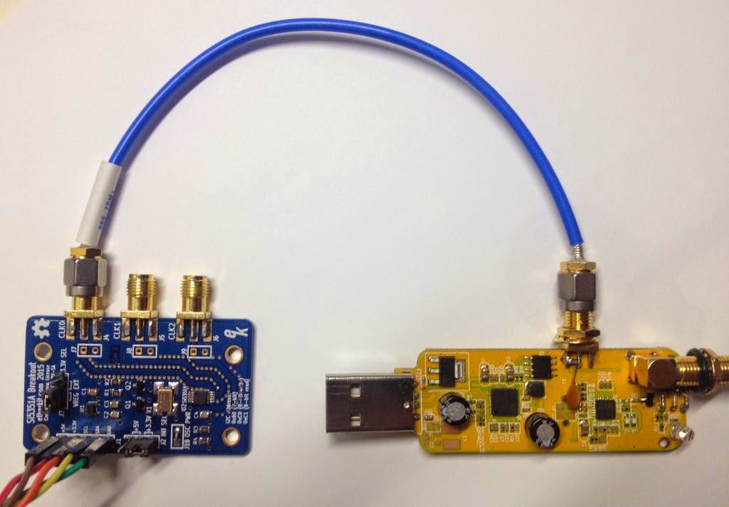
What you see here is @NT7S's Si5351a breakout board connected to the local oscillator of one of my DVB-T dongles. The DVB-T dongle with its 28.8 MHz crystal oscillator is normally not so frequency-stable because of the temperature drift of the frequency of the crystal. Inspired by this post by Simon Schrödle I've made the same setup (with a less expensive frequency generator). On the edge of the DVB-T dongle I've soldered an SMA edge connector by scraping a bit of the soldering mask for the ground connection.
Between the center pin and the ground is an 82 Ohm 0805 SMD resistor. Then the signal goes trough a 10nF capacitor to the place where the signal goes into the R820T mixer. For good measure I've removed both loading capacitors of the original crystal. With a sketch from https://github.com/etherkit/Si5351Arduino I generate the needed 28.8 MHz to the mixer. The mixer then feeds this signal to the RTL2832 chip that needs this signal to.

The 28.8 MHz from the breakout board is generated with a 25 MHz TCXO, so there is no temperature drift with this setup anymore. Also the 28.8 MHz programmed on in the sketch is dead on frequency, even so that I can receive stations in the 23cm band without having to tune the ppm offset in GQRX. With 0 ppm offset I've received a local 23cm repeater exactly on-channel.

The Si5351a can output different drive levels. With 8mA drive level you get about 3.3Volts on the R820T-chip, same as with a TCXO soldered directly to the DVB-T board as I've seen in other mods. By lowering the drive level to 2mA you get about 800mV, and the spurious signals that you see in your spectrum (every 28.8 MHz, e.g. 45x1296 MHz) will also be lower.

Another nice thing you can do is de-tune the oscillator a bit. In the picture below I alternate the oscillator between 28.800 and 28.801 MHz. If you do this you can shift all your signals that you receive on your antenna, but most of the spurious coming from the DVB-T dongle will stay in place. This way you can tune around any spurious signals that you get from the RTL2832 chip or the USB-connection. In my example case I would have been able to de-tune the oscillator to bypass large the spurious signal on 432MHz. Luckily the RTL-2832 chip operates just fine when the oscillator is de-tuned a bit as Simon already mentioned. Can you see al the signals shifting?


To do:
- Make graphs of the spurious level with normal and shifted oscillator.
- Make a proper low pass filter between oscillator and DVB-T dongle to see if I can reduce noise (the signal into the mixer is not a clean sine wave, as the Si5351a outputs a square wave).
- Make a script to use or alter rtl_power to make frequency plots with spurious-bypass option.

Any comments? 

First blog message.

Hello world,

Let me introduce myself.

My name is Milan van de Swaluw. At the moment I'm 37 years young, married and the father of two kids.
I live in Mijdrecht, The Netherlands. At the moment I'm mainly interested in hamradio (callsing PE1RYY), electronics, domotica and model quadcopter and helicopter flying. The electronics and domotica interest is the main reason why I wanted to put up a blog, as I have too many ideas to turn into successful projects. It would be a waste to not share my ideas with the world and let them end in a pile of junk on my workbench.

Hope you all enjoy my (probably not so frequent) write ups, and if you have any comments please share them. Sharing ideas is the reason why I start this.

Milan.